


Structural Effect of Solar Arrays on an Existing Structure


This is an exciting time to be part of the solar industry. Many people have begun to reap the benefits of incorporating solar into their homes and businesses. This means that not only are new buildings accommodating solar, but also many existing buildings are being retrofit to accommodate roof mounted photovoltaic arrays. Are potential solar customers being informed of the structural concerns associated with this type of retrofitting? Existing buildings should always be reviewed for their ability to support the loads associated with roof mounted photovoltaic arrays.
How do you verify the adequacy of your existing building to support these new loads? First, define the loads imparted on the photovoltaic arrays. Next, determine how the loads imparted by the arrays affect the structure, from roof to foundation. This is referred to as the load path. The phrase, "A chain is only as strong as its weakest link" holds especially true for a structure. Failures commonly occur because the load path wasn't followed properly.
Defining the Loads Imparted on the Arrays
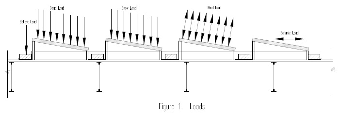
Current building codes provide for various combinations of loading, which includes dead, snow, wind, and seismic. The following list defines each load and how it affects the photovoltaic arrays, while Figure 1 shows how those loads are applied to the array.
Dead Loads
This is the self-weight of the photovoltaic array, which includes the racking components, the panel, and any ballast provided. Most photovoltaic racking is configured so that the panels are supported at each corner. That means the loads from the racking will be applied to the roof as concentrated loads. Beware of the average loads provided by the manufacturer; these are determined by dividing the total load of the array by the total area covered by an array, and are not an accurate depiction of the loading. Ballast is often distributed at corners and edges, where the upward wind load is higher. The resulting large concentrations of load can affect individual components of the roof.
Live loads
Per IBC 2015 section 1607.12.5.1: "the roof photovoltaic live load shall be in addition to the panel loading unless the area covered by each solar photovoltaic panel or module is inaccessible. Areas where the clear space between the panels and the rooftop is not more than 24 inches shall be considered inaccessible." In other words, for most low slope roof mounted arrays, live loads will not be applied in the areas where the arrays occur.
Snow Loads
Snow loads on arrays are increased slightly due to the use of a thermal factor for cold conditions - something not normally required on a warm roof. Arrays that are raised above the roof do not get the benefit of the warm roof to decrease the snow load.
Wind loads
ASCE 7 "Minimum Design Loads for Buildings and other structures" is referenced by IBC codes for determining the loads on a structure. Unfortunately, ASCE7-2010 and its predecessors do not adequately address the effects of wind on a photovoltaic panel mounted on a flat roof. However, there are other sources for determining wind loads on a roof-mounted panel. One such reference guide is published by the Structural Engineers Association of California (SEAOC) PV-2 2012 "Wind Design for Low-Profile Solar Photovoltaic Arrays on Flat Roofs." This guideline helps determine loads, but is considered conservative. However, it allows for the provision of approved wind tunnel studies for a specific product. Most PV racking manufacturers provide approved wind tunnel studies specific to their product, that are more accurate for their racking. While the upward wind forces determine the distribution of ballast to counteract the effects of these forces, another aspect of wind loading is often forgotten: the downward wind forces. In the aforementioned SEAOC PV-2 guide, Figure 29.9-1 shows the wind loads acting on the panels as either upward or downward; the accompanying note 1 says "1. (GCrn) acts towards and away from the panel's top surface" (GCrn is the nominal net pressure coefficient). This condition has been confirmed by wind tunnel testing, although testing may provide different coefficients than those used in SEAOC PV-2.
Seismic
Seismic loads are primarily lateral, but can impart a vertical load (which is defined as 0.2SdsD based on ASCE 7-10 section 12.4.2.2). This load is very small in comparison to wind load.
Determine the Loads Imparted by the Arrays to the Structure (Load Path)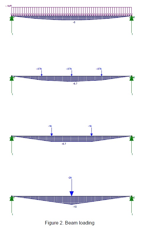
2012 IBC section 3403.3 allows for an increase in the gravity loads of an existing building by 5 percent, and section 3403.4 allows for an increase of forces to lateral load-carrying elements of no more than 10 percent. In 2015, the ICC adopted a separate code for existing buildings: the International Existing Building Code (IEBC). Sections 402.3 and 402.4 of the 2015 IEBC provides the same criteria as that noted above for the 2012 IBC.
Following the load path, we start with the application of the roof-mounted array to the roof decking. The decking should be checked for a concentrated load where the racking makes contact for downward and for net uplift when mechanical attachments are provided. This load is then transferred to the roof joists. The decking and the joists were originally designed based on uniform loads, but now must support the concentrated loads from the dead load of the arrays, and possible snow and or/wind loads.
Concentrated loads placed on a member (in lieu of uniform loads) can significantly increase the moment on a member. For instance, Figure 2 shows four different loadings on the same 20 foot long member, each of which equate to a total load of 2,000 lbs.
- Load 1 is uniform and a result in a moment of 5,000 lb-ft.
- Load 2 has three separate loads that total 2,000lbs, but provide a moment of 6,700 lb-ft.
- Load 3 has only two loads that result in the same moment as Load 2
- Load 4 has one load of 2,000 lbs which results in a moment of 10,000 lb-ft.
The resulting moments from concentrated loads increased 33 to 100 percent over the uniform loads. This loading is an exaggeration, but it helps to demonstrate the effects of concentrated versus uniform loading. If a joist is designed to its code required capacity, the placement of concentrated loads can result in an increase greater than the additional 5 percent allowed per the IEBC. The gravity loads to the beams, columns, and foundations must be checked by following the load path in a similar fashion. In addition, members should be checked for shear capacity as well as their supporting connections. Concentrated loads may exceed the shear capacity of members that were not designed for constant shear, such as open web steel bar joists.
The increase to the dead load of a building caused by adding arrays should be checked to determine if this will impact the lateral system due to seismic loading. Per IEBC 402.4, if the new total dead load of the building has not increased over the existing total dead load by more than 10 percent, then the additional forces from seismic loading need not alter the existing lateral framing.
Conclusion
When adding photovoltaic arrays to an existing building, we must ensure that the building can support these additional loads. A licensed structural engineer should always be engaged to verify an existing structure's capacity. While it is indeed an exciting time to be part of the solar industry, it's equally important to provide a safe solution for the public's energy needs.
Christine Wrobel is a Structural Engineer at Larson Engineering, Inc.
Larson Engineering | www.larsonengr.com
Volume: 2017 July/August
.jpg?r=2913)
.gif?r=7634)

.jpg?r=9533)